R 2 requires the high cut-off frequency F H and the. Even mode Losslen 00808908.

Design Coupled Line Bandpass Filter Part 2 Simulation Youtube
An application of this circuit is a graphic equalizer created by feeding a signal to a number of parallel band-pass filters each tuned to a different frequency.

. Port 1 of the first segment and Port 4 of the last segment are designated as the input and output ports. BW Bandwith of the filter for unit gain. Designing a Coupled Line Bandpass Filter.
Generally coupled line inputs are fine for narrow band. Center frequency gain K0 center frequency f0 cutoff frequency fL and fH passband width BW and quality factor Q. The first part of this circuit comprised of resistor R1 and capacitor C1 compose the high-pass filter.
The bandpass coupled line filter presented here is specified to have a midband at 169GHz and bandwidth of 0169GHz. The geometry is analysed by using Computer Stimulation Techniques CST software. These graphs are for symmetrical strip line in the form shown in Fig.
This design has the. Negative capacitances indicate an unhappy inductance. Uses 22 pF SQCB low ESR capacitors from ACX RF TOKO LL2012-FHL Chip Inductors muRata 3-10 pF Trimmer and a wire capacitor for coupling.
Where C1 C2 C Capacitors. Design Data for a 2-Resonator Bandpass Filter. A bandpass filter is a filter that can pass frequencies in a particular frequency band and attenuate all other transmitted signals outside the band.
From 1 to 9 Cutoff frequency Fc MHz Passband. A tapped structure is chosen for the external couplings. The equations by Bradley and Cohn in the reference cited are used here to construct graphs for determining band-pass filter dimensions as a function of normalized bandwidth.
This means that the output signal is exactly in phase with the input signal. When it comes to GHz frequency range the coupled-line microstrip bandpass filter is. Popular and relatively practical to design.
Note that X or em-based models are used wherever possible for better accuracy in the filter design. R1 R2 R3 Resistors. I am trying to design a microstrip bandpass filter in ADS with a center frequency of 24GHz and a fractional BW of 10.
Transmitted and received signals have to be filtered at a certain center frequency with a specific bandwidth in this paper a coupled-line bandpass Filter at the center frequency 6 GHz with the. A bandpass filter is a filter that can pass frequencies in a particular frequency band and attenuate all other transmitted signals outside the band. A Coupled-Line Microstrip Filter is designed for centre frequency 24GHz and it is made up of FR-4 material having permittivity r44.
Q Quality Factor of the filter for unit gain. Show activity on this post. This calculator is for an active noninverting op amp bandpass filter.
F c center frequency of the filter for unit gain. Thi op amp bandpass filter produces a noninverting signal at the output. Passband insertion and return loss is.
The main performance parameters of the bandpass filter are. Select Chebyshev Elliptic Butterworth or Bessel filter type with filter order up to 20 and arbitrary input and output impedances. My results from the schematic look great.
Coupled Line Bandpass Filter. When I move to the layout and EM simulation my results look nothing close to a bandpass filter. Coupled-line microstrip bandpass filters are easy to design for narrow bands but for relatively large band it becomes complex as more parameters are need to be considered.
MHz Impedance Zo Z Ripple. This video explain about how to calculate the value of admittance intervals and o. This video shows calculation method on design coupled line bandpass filter.
This paper presents the design and test of a planar coupled line filter constructed from relatively high quality dielectric material. LC Filter Design Tool Calculate LC filters circuit values with low-pass high-pass band-pass or band-stop response. As an example a compact tri-band parallel-coupled-line bandpass filter with suppression of second harmonic frequency was implemented operating at 193246 GHz to cover PCS1900 WiMAX and C.
R 1 requires the low cut-off frequency F L and the capacitance of C 1. Odd mode Loss 00740294. INTRODUCTION Parallel coupled transmission-line filter in microstrip and stripline technology are very common for implementation of bandpass and band-stop filters with required bandwidth up to a 20 of central frequency.
The main performance parameters of the bandpass filter are. The band pass filter resistor calculator can be used to calculate the values of resistors needed to create a filter with a specific cut-off frequencies F L and F H. Other formulas are available to design end-coupled filters up to approximately the same bandwidths.
Calculation of each resistor value requires two inputs. Center frequency gain K0 center frequency f0 cutoff frequency fL and fH passband width BW and quality factor Q. Number of LC pairs.
This project the design of bandpass filter at the frequency of 24 GHz with parallel-coupled microstrip will be implemented. In this part of the tutorial lesson you will cascade four quarter-wavelength Generic Coupled T-Line segments to build a distributed bandpass filter as shown in the opposite figure. The MWO Transmission Line Calculator Next a schematic diagram of the filter is constructed as in fig 3.
Nowadays microstrip bandpass filters designed from coupled line have been widely used in many wireless communication applications. Coupled line filter demonstrate the fourth order of the Chebyshev elements and its response corresponds to bandpass filter. Please verify by simulation that attenuation above passband is sufficient.

1 Parallel Coupled Band Pass Filter At 3 2 Ghz Results Using Tool Download Scientific Diagram

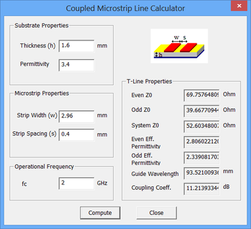
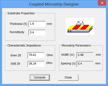
Parallel Coupled Band Pass Filter Calculator First Interface Download Scientific Diagram
Rf Tutorial Lesson 7 Designing Distributed Bandpass Filters Using Coupled Transmission Line Segments Emagtech Wiki

Coupled Line Bandpass Filters Youtube
Rf Tutorial Lesson 7 Designing Distributed Bandpass Filters Using Coupled Transmission Line Segments Emagtech Wiki

Design Coupled Line Bandpass Filter Using Puff Youtube
Schematic Circuit Of Parallel Coupled Microstrip Bpf With Agilent Ads Download Scientific Diagram

1 Parallel Coupled Band Pass Filter At 3 2 Ghz Results Using Tool Download Scientific Diagram
0 comments
Post a Comment